POST-UMC: SCAPA and HIGHLANDER
It is easy to divide everything subsea from the early days of the UK sector as before and after Shell/Esso’s Underwater Manifold Centre (UMC), which was deployed on the Central Cormorant field. Except maybe not, at least philosophically.
Shell/Esso, or Shell UK Expro as it was known in those days, was pioneering. In the history of the offshore business, there have only ever been two projects in which an operator chose to use a development concept and technology that was unnecessary to achieve production from a field. The first was the UMC, which was developed using a subsea system in 500 feet (150m) water depth that the two big companies believed was going to be required in the future for deeper waters, seen then as 1,500 feet (457m). The second was the tension leg platform that Conoco installed in 148m on the Hutton field, also in the UK sector. Again, a concept, this one a dry well facility, designed for much deeper waters, although the second deployment at Snorre in Norway, was deeper (300m+) but not as deep as would be done later.
So what followed on directly from the UMC were Occidental/Scapa and Texaco/Highlander. They came onstream in 1985/86, a year or so after SEN was born and two after the UMC came into operation, which means that both were in the design phase before the Shell/Esso development was completed. So while Texaco and Oxy would have known about the UMC, they could not have necessarily used the same design philosophy, any of the new technology nor benefited from operational experience on that groundbreaking system.
What is most remarkable is that all three systems – each more than 35 years since installation – remain in production which is a testament to their robust design and fabrication. Some, though, might suggest that this reflects over-engineering, but it would be hard to argue with their longevity.
I want to digress for a moment. I mentioned in the intro to this series that there was an increasing amount of subsea production in Brazil in the 1980’s, but not worth a major mention. Certainly Petrobras was edging its way into deeper waters, but it was being done one well at a time with each having its own flexible riser. It was years before Petrobras ventured into manifolding, ie fluid gathering from more than one well, primarily because it wanted to be able to test each well on a regular basis after it came onstream. Of course, it is possible to well test using a manifold, but it does require additional pipework and would necessitate a separate riser to allow flow testing distinct from other production. An example of how Petrobras thought, it had – maybe still has – a semi production unit on Albacora Leste with nearly 80 risers and umbilicals hung off it. Here is a photo of this amazing system.

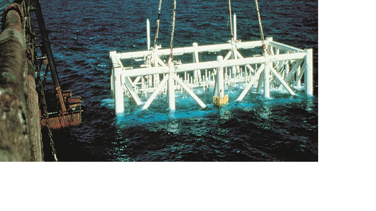
Back to the UK. Scapa was not Oxy’s first foray into subsea. It already had dipped its toe in the water with two subsea water injection templates (north and south) installed on the Claymore field, but it was being way more ambitious with Scapa. This was a large template-manifold (over 900t) linked back to the Claymore platform with twin 4.5km pipeline bundles, possibly the first ever used in the UK, built by Kestrel Marine and installed by Smit.
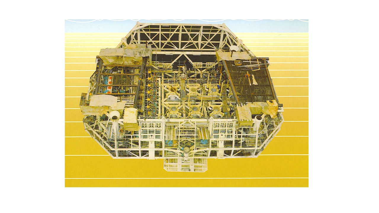
If you look at the Scapa system, it is easy to be impressed considering when it was designed and fabricated. The template-manifold was engineered to provide a high level of protection for each of the eight well slots which is why it is so big (40m by 35m by 10m). There was also a tremendous amount of redundancy, probably for fear of the unknown. For example, the twin production bundles, the two smaller chemical service bundles and the two umbilicals would likely now be limited to one each. As is often said now, redundancy does not always equal reliability nor availability.

What is really impressive though – and could easily be overlooked – is the operational philosophy. It is quite common nowadays for operator’s to make use of existing infrastructure. At the recent Subsea Expo conference, a speaker from Neptune Energy said that the economics for its upcoming Seagull project in the UK are bolstered by making use of seabed facilities already in place as part of BP’s ETAP development. Oxy did it more than 35 years ago. The injection water for Scapa and the control of that portion of the system were provided by a spur line from the South Claymore template, reducing the length of both the pipeline and the umbilical. Money saved and complexity reduced. All very contemporary.
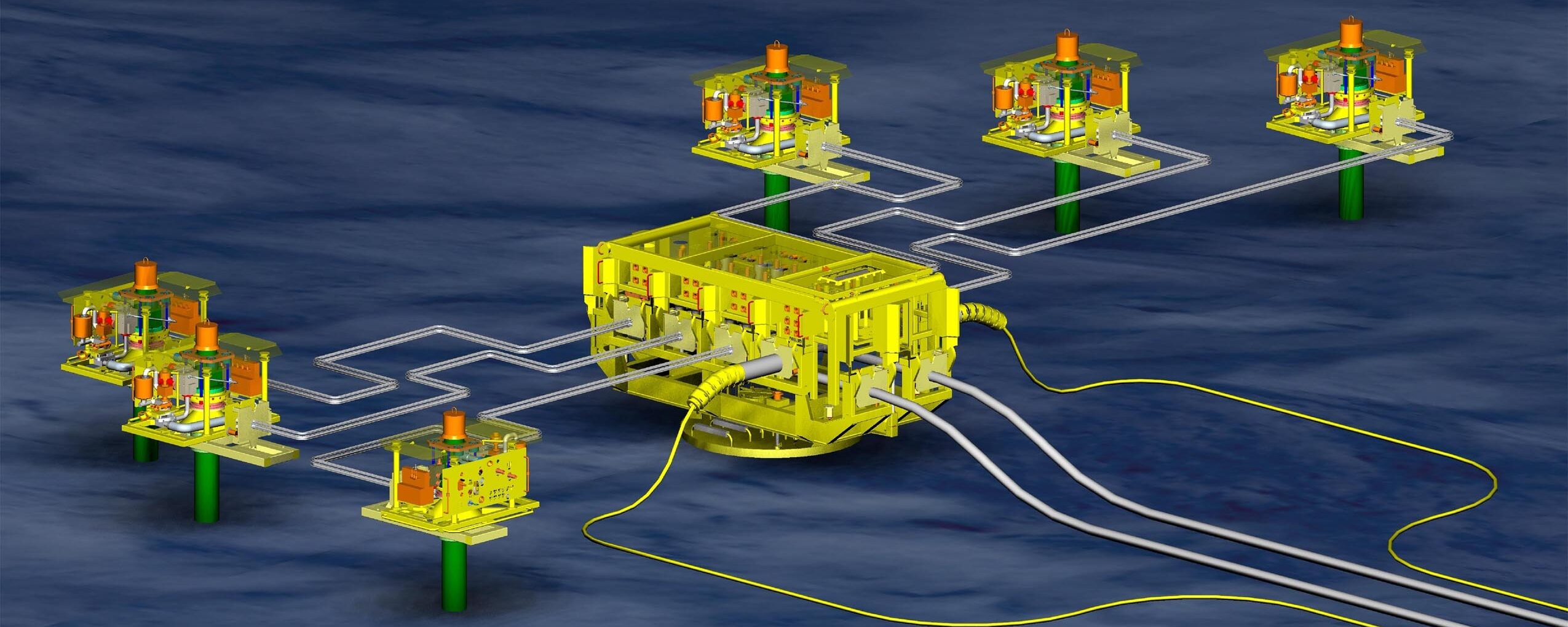
It is worth noting, in the context of the UMC, what was not done at Scapa and what was. The control system (NL Shaffer) was direct hydraulic – the electro-hydraulic system used at the UMC was a first and probably considered unproven – and required 56 hydraulic hoses in the umbilicals to handle all of the valves. What a beast that umbilical must have been. The xmas trees were supplied by Hughes Offshore. What the Scapa template-manifold did include was the ability to tie-in both on-template and satellite wells, also a feature of the UMC.
The Highlander system, including a bigger (1,200t) template-manifold, was an even more impressive engineering achievement. So much so that now nearly 40 years later, Fluor still uses it to promote its engineering expertise, despite that fact that there can not be any engineers on its staff who worked on that project.

Texaco was very keen to make Highlander a success as it was aware that its reputation had been tarnished by the long held belief around the North Sea that its Tartan platform, the host for Highlander and later Petronella, was installed in the wrong location relative to the reservoir. This should not in any way, though, detract from Texaco’s ambition at Highlander. The design basis included a number of firsts, although it must be admitted there were few big subsea projects before it. The technology notables included a subsea slugcatcher; both water and gas injection; well testing facility; and the use of electric submersible pumps to lift the oil to the surface.
In addition, at eight miles, it was a significant tieback distance – nearly twice that of the UMC and three times tht of Scapa to their hosts – although by comtemporary standards, it is a near neighbour. The other challenge was a much smaller reserve base (15mmbbls) compared with Central Cormorant (130mmbbls) and Scapa (~120mmbbls).
Texaco did not stop with this first phase. Years later, it installed the industry’s first multiphase meter on the seabed near Tartan for measuring fluids from Highlander (see photo from previous blog, ‘Back to the Future’).
These projects set the stage for what would come in the next several decades. One of the biggest lessons learned was not to have such big structures. Designers aimed for more slimmed down production facilities which probably also led to the decoupling of wells from manifolds, such as was done at Troll West by Norsk Hydro, but that is a story for another day.


2 thoughts on “HISTORY OF SUBSEA: PART II”
Hi Steve. I understand your reasons for starting your history in the “post-UMC” era, but I think to do it justice you should try to develop some sort of “prequel” that sets the scene. The Cormorant UMC in the UK (and Gullfaks in Norway) played a key role in the subsequent rapid expansion of Subsea for field development because of their innovative approach to subsea production control and data acquisition. The use of Electro-Hydraulic Multiplex control systems (derived from the avionics industry) on these developments was a real game-changer because it enabled control of subsea production equipment over much longer distances than could previously be achieved and also allowed data from the field to be collected in real-time (I’m sure a few old hands out there will have a view). Many later innovations such as Intelligent Completions and Subsea Processing would not have been possible without the technology that was first introduced on UMC and Gullfaks. So for me these would be the starting point of Subsea History Part II rather than the end of Part I.
But it’s your blog and your history…
Hi Tony :
Most of the early subsea production system where relatively small distances and stand alone wells, ex exploration ones. The controls where straight hydraulic, piloted hydraulic ,and later programable sequential hydraulics. Most of that equipment was ex Subsea BOP controls (Koomey/ Cameron Payne) When electrical signalling / data acquisition ect .. was introduced an electrical wire was run in parralel to the hydraulic umbilical. I have use Schlumberger type logging cable (negative buoyancy and strong for laying) attach to the subsea tree. Then as you say the avionics came in with their kit and experience , hence formation and monitoring of industrial knowledge and packaging , Ferranti/FSSL , Matra/Alsthom , Marconi, Lockheed ect ..The greatest challenge was the mating of the electrics ! often the weakest link. An experiment in the Gulf of Mexico used a tiny nuclear cell /source to power one subsea tree as an R & D idea, not pursued because of the risk of such subsea source.
The implementation of large subsea template enable to think the same way in the control logic, where one computer + one umbilical can operate 8 wells and monitor all the bits added , chokes, DHPT,flow sensors, corrosion probes, valve positions indic. Other ideas where surface telemetry with the hydraulic supply buoy above the template ? so umbilical length = water depth. I am aware of full electric systems but I have never worked on one.